-
Introduction
FIFO is an acronym for First In First Out, which describes how data is managed relative to time or priority. In this case, the first data that arrives will also be the first data to leave from a group of data. A FIFO Buffer is a read/write memory array that automatically keep track of the order in which data enters into the module and reads the data out in the same order. In hardware FIFO buffer is used for synchronization purposes. It is often implemented as a circular queue, and has two pointers:
Read and write addresses are initially both at the first memory location and the FIFO queue is Empty. When the difference between the read address and write address of the FIFO buffer is equal to the size of the memory array then the FIFO queue is Full.- Read Pointer/Read Address Register
- Write Pointer/Write Address Register
FIFO can be classified as synchronous or asynchronous depending on whether same clock (synchronous) or different clocks (asynchronous) control the read and write operations.
A synchronous FIFO refers to a FIFO design where data values are written sequentially into a memory array using a clock signal, and the data values are read out sequentially from the memory array using the same clock signal. Figure 1 shows the flow of the operation of a typical FIFO.
Synchronous FIFO

Figure 1. Operation of FIFO with the three data values -
Verilog Module
Figure 2 presents the Verilog module of the FIFO Buffer. This FIFO Buffer can store eight 32-bit values. The FIFO Buffer module consists of a 32-bit data input line, dataIn and a 32-bit data output line, dataOut. The module is clocked using the 1-bit input clock line Clk. The module also has a 1-bit enable line, EN and a 1-bit active high reset line, Rst.
The 1-bit RD line is used to signal a data read operation on the FIFO Buffer and the 1-bit WR line is used to signal a data write operation on the FIFO Buffer. Both the RD and WR lines are active high. The module also has two output lines FULL and EMPTY which are each 1-bit wide. The FULL line becomes high when the FIFO Buffer is or becomes full (internal counter becomes eight). The EMPTY line becomes high when the FIFO Buffer is or becomes empty (internal counter becomes zero).
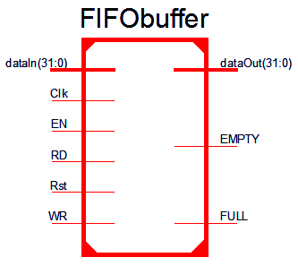
Figure 2. Verilog module of a FIFO Buffer -
Verilog Code for the FIFO Buffer (FIFObuffer.v)
- module FIFObuffer( Clk,
- dataIn,
- RD,
- WR,
- EN,
- dataOut,
- Rst,
- EMPTY,
- FULL
- );
- input Clk,
- RD,
- WR,
- EN,
- Rst;
- output EMPTY,
- FULL;
- input [31:0] dataIn;
- output reg [31:0] dataOut; // internal registers
- reg [2:0] Count = 0;
- reg [31:0] FIFO [0:7];
- reg [2:0] readCounter = 0,
- writeCounter = 0;
- assign EMPTY = (Count==0)? 1'b1:1'b0;
- assign FULL = (Count==8)? 1'b1:1'b0;
- always @ (posedge Clk)
- begin
- if (EN==0);
- else begin
- if (Rst) begin
- readCounter = 0;
- writeCounter = 0;
- end
- else if (RD ==1'b1 && Count!=0) begin
- dataOut = FIFO[readCounter];
- readCounter = readCounter+1;
- end
- else if (WR==1'b1 && Count<8) begin
- FIFO[writeCounter] = dataIn;
- writeCounter = writeCounter+1;
- end
- else;
- end
- if (writeCounter==8)
- writeCounter=0;
- else if (readCounter==8)
- readCounter=0;
- else;
- if (readCounter > writeCounter) begin
- Count=readCounter-writeCounter;
- end
- else if (writeCounter > readCounter)
- Count=writeCounter-readCounter;
- else;
- end
- endmodule
Figure 3. Verilog code for FIFO Buffer -
Verilog Test Bench for FIFO Buffer (FIFObuffer_tb.v)
- `timescale 1ns / 1ps
- module FIFObuffer_tb;
- // Inputs
- reg Clk;
- reg [31:0] dataIn;
- reg RD;
- reg WR;
- reg EN;
- reg Rst;
- // Outputs
- wire [31:0] dataOut;
- wire EMPTY;
- wire FULL;
- // Instantiate the Unit Under Test (UUT)
- FIFObuffer uut (
- .Clk(Clk),
- .dataIn(dataIn),
- .RD(RD),
- .WR(WR),
- .EN(EN),
- .dataOut(dataOut),
- .Rst(Rst),
- .EMPTY(EMPTY),
- .FULL(FULL)
- );
- initial begin
- // Initialize Inputs
- Clk = 1'b0;
- dataIn = 32'h0;
- RD = 1'b0;
- WR = 1'b0;
- EN = 1'b0;
- Rst = 1'b1;
- // Wait 100 ns for global reset to finish
- #100;
- // Add stimulus here
- EN = 1'b1;
- Rst = 1'b1;
- #20;
- Rst = 1'b0;
- WR = 1'b1;
- dataIn = 32'h0;
- #20;
- dataIn = 32'h1;
- #20;
- dataIn = 32'h2;
- #20;
- dataIn = 32'h3;
- #20;
- dataIn = 32'h4;
- #20;
- WR = 1'b0;
- RD = 1'b1;
- end
- always #10 Clk = ~Clk;
- endmodule
Figure 4. Verilog Test-bench for FIFO Buffer -
Timing Diagram

Figure 6. Timing Diagram of FIFO Buffer
First-In-First-Out Buffer


Subscribe to:
Posts (Atom)