-
Introduction
In low level programming, we mostly manipulate data that is present in registers. Registers are units of memory which are closely coupled with the processor core (ALU) and in most architectures the ALU operations are carried out on these registers and the results obtained are also stored in them. Registers are a limited resource and efficient management of registers is a key issue in low level programming. Processors must carry out a large number of functions utilizing the limited number of registers available. In order to do so, the registers are used to store the data values that are required by the current function being executed on the processor and not all the data values of all the functions which are currently in inactive states. Instead the data values of inactive functions are stored in a special area of memory known as the stack.
A stack is a reserved area in the memory which is used by the processor to store data that is not being used currently by the processor but is still is required future processing steps. Stack memories are useful when there is a need to call a subroutine function. If the registers used by the subroutine were being used in the calling portion of the program, then they cannot be erased. Upon returning to the calling portion of the program these registers should have the same values that they had before the subroutine call and not the values of the variables used in the subroutine. When a processor switches between tasks in a multitasking environment then a context of the all the tasks that are not currently running must be stored to allow for the switching back to them. This is done by storing the context of the inactive tasks in the stack.
Stacks are implemented as Last In First Out (LIFO) Buffers. The term PUSH to stack means putting data in the stack and the term POP from stack means removing the data from the top of stack (TOS)
The push and pull operations for a stack are described below:
Push Operation
Steps:
- Decrement Stack Pointer
- Push/Write Data to the top of the stack
Pop Operation
Steps:
- Pop/Read Data from the top of the stack
- Increment the Stack Pointer
-
Verilog Module
Figure 1 presents the Verilog module of the LIFO Buffer. This LIFO Buffer can store sixteen 32-bit values. The LIFO Buffer module consists of a 32-bit data input line, dataIn and a 32-bit data output line, dataOut. The module is clocked using the 1-bit input clock line Clk. The module also has a 1-bit enable line, EN and a 1-bit active high reset line, Rst.
The 1-bit RW line is used to select between LIFO read (POP) and LIFO write (PUSH) operations. If the RW line is high then POP operation is selected and if RW line is low then PUSH operation is selected. The module also has two output lines FULL and EMPTY which are each 1-bit wide. The FULL line becomes high when the LIFO Buffer is or becomes full (internal stack pointer counter becomes zero). The EMPTY line becomes high when the LIFO Buffer is or becomes empty (internal stack pointer counter becomes sixteen).

Figure 1. Verilog module of LIFO Buffer -
Verilog Code for LIFO Buffer (LIFObuffer.v)
- module LIFObuffer( dataIn,
- dataOut,
- RW,
- EN,
- Rst,
- EMPTY,
- FULL,
- Clk
- );
- input [3:0] dataIn;
- input RW,
- EN,
- Rst,
- Clk;
- output reg EMPTY,
- FULL;
- output reg [3:0] dataOut;
- reg [3:0] stack_mem[0:3];
- reg [2:0] SP;
- integer i;
- always @ (posedge Clk)
- begin
- if (EN==0);
- else begin
- if (Rst==1) begin
- SP = 3'd4;
- EMPTY = SP[2];
- dataOut = 4'h0;
- for (i=0;i<4;i=i+1) begin
- stack_mem[i]= 0;
- end
- end
- else if (Rst==0) begin
- FULL = SP? 0:1;
- EMPTY = SP[2];
- dataOut = 4'hx;
- if (FULL == 1'b0 && RW == 1'b0) begin
- SP = SP-1'b1;
- FULL = SP? 0:1;
- EMPTY = SP[2];
- stack_mem[SP] = dataIn;
- end
- else if (EMPTY == 1'b0 && RW == 1'b1) begin
- dataOut = stack_mem[SP];
- stack_mem[SP] = 0;
- SP = SP+1;
- FULL = SP? 0:1;
- EMPTY = SP[2];
- end
- else;
- end
- else;
- end
- end
- endmodule
Figure 2. Verilog code for LIFO Buffer -
Verilog Test Bench for LIFO Buffer (LIFObuffer_tb.v)
- `timescale 1ns / 1ps
- module LIFObuffer_tb;
- // Inputs
- reg [3:0] dataIn;
- reg RW;
- reg EN;
- reg Rst;
- reg Clk;
- // Outputs
- wire [3:0] dataOut;
- wire EMPTY;
- wire FULL;
- // Instantiate the Unit Under Test (UUT)
- LIFObuffer uut (
- .dataIn(dataIn),
- .dataOut(dataOut),
- .RW(RW),
- .EN(EN),
- .Rst(Rst),
- .EMPTY(EMPTY),
- .FULL(FULL),
- .Clk(Clk)
- );
- initial begin
- // Initialize Inputs
- dataIn = 4'h0;
- RW = 1'b0;
- EN = 1'b0;
- Rst = 1'b1;
- Clk = 1'b0;
- // Wait 100 ns for global reset to finish
- #100;
- // Add stimulus here
- EN = 1'b1;
- Rst = 1'b1;
- #40;
- Rst = 1'b0;
- RW = 1'b0;
- dataIn = 4'h0;
- #20;
- dataIn = 4'h2;
- #20;
- dataIn = 4'h4;
- #20;
- dataIn = 4'h6;
- #20;
- RW = 1'b1;
- end
- always #10 Clk = ~Clk;
- endmodule
Figure 3. Verilog Test-bench for LIFO Buffer -
Timing Diagram
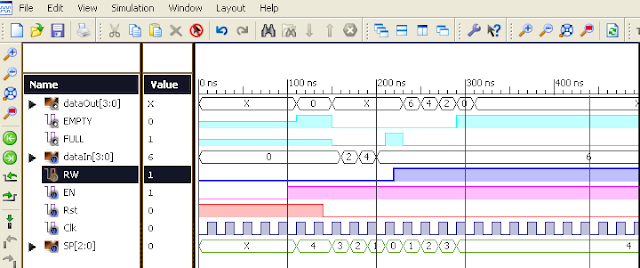
Figure 4. Timing Diagram of LIFO Buffer
Last-In-First-Out Buffer


Subscribe to:
Posts (Atom)