-
Introduction
A full adder adds two 1-bit binary numbers along with 1-bit carry-in thus generating 1-bit sum and 1-bit carry-out. If A and B are two 1-bit values input to the full adder and Cin is the carry-in from the preceeding significant bit of the calculation then the sum, S, and the carry-out, Cout, can be determined using the following Boolean expressions.
S = A xor B xor Cin
Cout = (A and B) or (B and Cin) or (Cin and A)
The full adder is usually a component in a cascade of adders, which add 4, 8, 16, 32 bit binary numbers.
The gate level design of a full adder is shown in Figure 1.
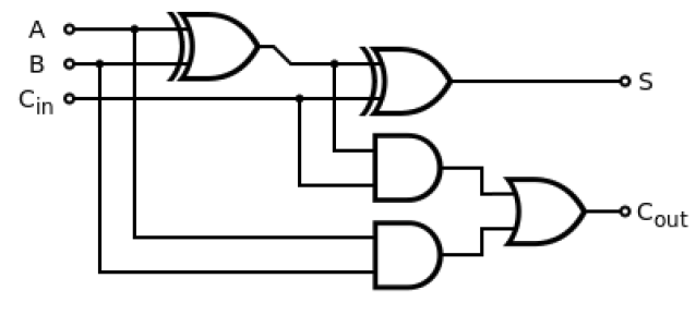
Figure 1. Gate-Level Design of a Full Adder -
Truth Table
The truth table of a typical full adder is shown in Figure 2. In the truth table A, B and Cin are the three input signals and S and Cout are the output signals.

Figure 2. Truth table of a Full Adder. -
Verilog Module
The Verilog module of full adder is shown in Figure 3. The module has three 1-bit input ports as A, B, and Cin. There two output ports as S, and Cout which are also 1-bit wide.

Figure 3. Verilog module of a Full Adder
-
Verilog Code of the Full Adder (fullAdder.v)
- `timescale 1ns / 1ps
- module fullAdder ( In1,
- In2,
- Cin,
- Sum,
- Cout
- );
- input In1,
- In2,
- Cin;
- output Sum,
- Cout;
- assign Sum = (In1 ^ In2) ^ Cin;
- assign Cout = (In1 & In2) | (In2 & Cin) | (Cin & In1);
- endmodule
Figure 4. Verilog Code for Full Adder -
Verilog Code of the Test Bench of the Full Adder (fullAdder_tb.v)
- `timescale 1ns / 1ps
- module fullAdder_tb;
- // Inputs
- reg In1;
- reg In2;
- reg Cin;
- // Outputs
- wire Sum;
- wire Cout;
- //Temporary looping variable
- reg [2:0] i = 3'd0;
- // Instantiate the Unit Under Test (UUT)
- fullAdder uut (
- .In1(In1),
- .In2(In2),
- .Cin(Cin),
- .Sum(Sum),
- .Cout(Cout)
- );
- initial begin
- // Initialize Inputs
- In1 = 1'b0;
- In2 = 1'b0;
- Cin = 1'b0;
- // Wait 100 ns for global reset to finish
- #100;
- // Add stimulus here
- for = 0; i < 8; i = i + 1'b1)begin
- {In1,In2,Cin} = {In1,In2,Cin} + 1'b1;
- #20;
- end
- end
- endmodule
Figure 5. Verilog Test-bench for Full Adder -
Timing Diagram

Figure 6. Timing Diagram of Full Adder
Full Adder


Subscribe to:
Posts (Atom)